How to Read Mv on a Multimeter
In one case yous offset designing your own projects, using either a breadboard or stripboard, the circuits get more complicated and you will probably observe that you lot have made pocket-size errors and things do not e'er piece of work every bit you expected, hither is where you lot need to acquire how to utilise a multimeter to assist troubleshoot your project.
Information technology may be your code or it may exist your circuit. Why is that LED coming on dimly when that one lights up fully or why does that LED never calorie-free up? If it is a circuit problem y'all are probably going to need a multimeter to help runway down the fault. This tutorial is aimed at beginners to electronics and will show you how to read voltage, electric current, resistance, and check for continuity.
Donald Macadie, a British Post Office engineer, maintaining telecommunication equipment early in the 1920s, has been attributed with the invention of a single instrument that could mensurate amps, volts, and ohms. Information technology was later developed and sold as the AVOmeter – Amps-Volts-Ohms. It contained a moving coil meter, precision resistors with various sockets and switches to select the advisable mode and range. A mirror behind the needle was included to aid accurate readings from the needle.
This useful tool goes by several other names: multitester, or VOM (volt-ohm-milliammeter). They may exist analog (with a moving needle and several scales) or digital with a numeric LCD screen. The lower price and greater precision of the digital meters have made the analog versions obsolete.
The Analog Multimeter
This is a photo of my original multimeter, bought in 1977. It still works perfectly.
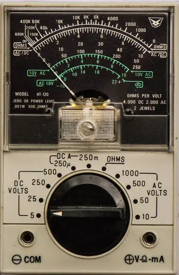
Information technology looks quite complicated with the 4 scales and vi sets of values applied to the scales. A punch switch is used to select DC voltage (4 ranges), DC current (2 ranges), Ohms and Air-conditioning voltage (4 ranges). Note the reversed logarithmic resistance scale at the tiptop, while the others are linear, increasing left to correct.
Luckily for us, the new digital meters are much easier to understand and read. Most automatically select the right range for many readings.
The prices vary from about $10 upwardly to the thousands for high precision and accurately calibrated laboratory models. For our purpose, a multimeter priced about $25 will do the job perfectly.
Using a Digital Multimeter
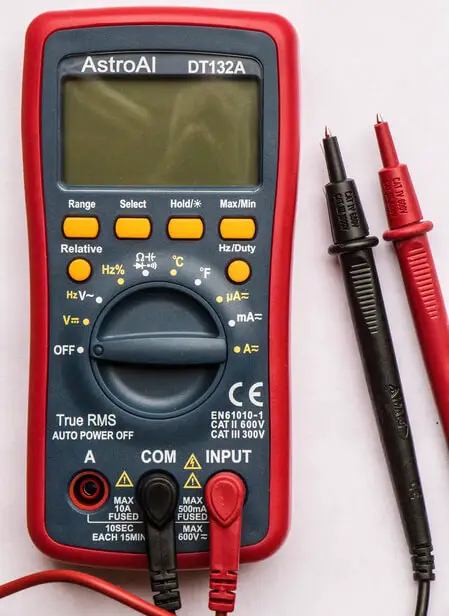
For this article, I'm going to be using an AstroAI Digital Multimeter DT132A, which I found on Amazon for about £21. It can do all the essentials: read voltages, currents, resistance, and check continuity.
Part of a Multimeter
A modern multimeter has four parts:
- Probes – insulated wires with pointed tips
- Ports – where the probes plug into the meter
- Controls – a rotary selection switch and buttons
- Liquid Crystal Display – oftentimes with a backlight
With the meter you receive two very well insulated probes colored red and black. These are plugged into the meter with the black lead in COM (common) and the blood-red probe in INPUT. They are both just wires with user protection/insulation and would work just equally well plugged into the reverse sockets. The BLACK probe is normally connected to GND and the Cherry used to read a higher voltage.
The tips of these probes can be further exposed by removing their insulating caps. This is not recommended when working with high voltages (dangerous) or closely packed components of different heights, to reduce the chances of brusk circuits. You may have to motility the RED probe to a dissimilar port when taking sure readings. (With this meter to measure currents > 200mA the A port should be used. Always read the manual)
Nosotros volition be using the meter with very low voltages, typically 5V or iii.3V, and with very small currents, typically milliamps. Resistance could be anything from 0 to Mega Ohms.
The display starts up with a very short display of all the symbols bachelor. Other makes and models of multimeters use the same symbols.
The 3rd push from the left can be used to turn ON/OFF the display backlight.
The Multimeter Liquid Crystal Display
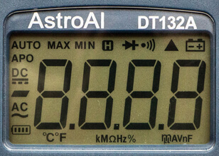
Starting at the bottom left we have:
- a battery indicator for the internal batteries, used for powering the instrument, measuring resistance, and driving the LCD display.
- Air conditioning and the wavy line indicates Alternating Electric current (from a main powered wall socket – Dangerous).
- Minus sign for negative values.
- DC with the straight and dotted line indicates Direct Current (from a battery).
- APO – Car Power OFF – saves the internal bombardment – near 15 minutes.
- Car – automated ranging – scaling of units – volts or millivolts, etc – very useful
- MAX and MIN – maximum or minimum value over time
- H – concord the current value on the brandish
- Diode Exam
- Continuity Exam – with beep
- Relative Examination
- Low battery indicator – change the batteries.
Unit of measurement mensurate
Along the bottom we have the units being measured – left to right
- Temperature in C and F, kilo, Mega, Ohm, Hz, % and micro, milli, Amps, Volts, nano and Farads.
This model too included a K type thermocouple for measuring temperatures. Without probes or thermocouple fitted information technology displays ambient temperature in °C or °F.
The Departure Netween DC and Ac
DC comes from batteries, a USB port, or a rectified ability supply (straight current – always flowing in the same management from positive to negative). Air conditioning comes from a dynamo or wall power indicate (alternating current which switches management 50 or 60 times a second). Information technology tin be very dangerous because the voltage is then loftier and can provide high current.
Measuring the Voltage of a Battery
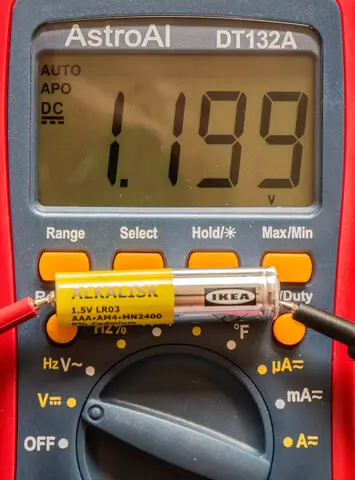
We turn the selector switch one click clockwise from OFF to DC voltage (V with a directly line). The RED probe is pressed to the positive cease of the battery and the BLACK probe to the negative terminate. The voltage is shown, automatically scaled to bespeak this bombardment is but supplying 1.199 volts and should exist replaced.
To read a voltage we put the meter in parallel with the object nosotros are measuring the voltage difference across.
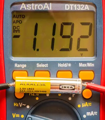
If we effort a dissimilar bombardment, only put the probes on the wrong ends we get a negative reading only the absolute value is correct.
Trying again with an old 9V bombardment.
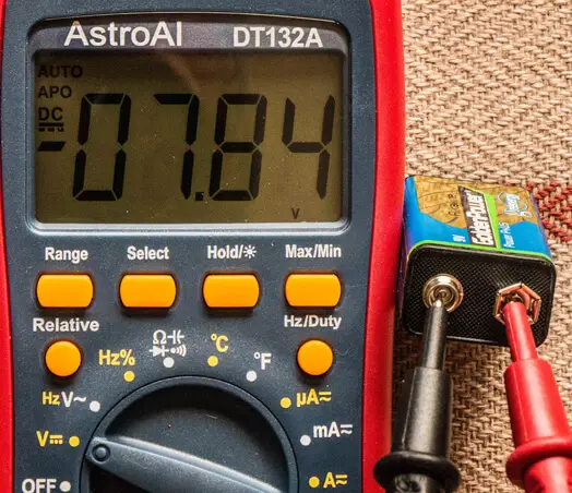
I picked the incorrect terminals again merely the unsigned value is correct.
Notice the AUTO in the height left corner showing that auto ranging is ON. The display was showing millivolts at start-up just quickly changed range automatically.
With machine-ranging, it may accept a short fourth dimension for the display to settle. This is well worth the short delay and is quicker and easier than having to manually select a different range. APO showing indicates that information technology will Automobile Power OFF, to save the internal battery of the meter if I forget to switch information technology off. This takes about fifteen minutes so it is expert do to turn the selector switch back to OFF as soon as you take taken the reading.
Reading AC voltages
Plough the rotary selector one more click clockwise to select Alternate Electric current (V with a wavy line). This is as well motorcar-ranging but starts with Volts.
If you really need to check the AC voltage at a wall socket (this is dangerous and so I practise not recommend information technology) simply plow the selector switch to the second position (HzV~) and use the probes very carefully on the live and neutral sockets. Keep your fingers well abroad from the metal tips of the probes
Measuring Resistance
Turn off and disconnect circuit before checking
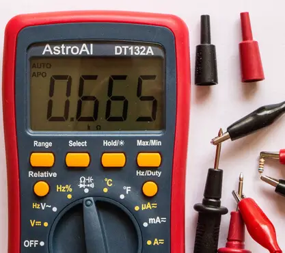
In the by I have establish a pair of insulated croc-prune wires extremely useful, especially when reading the values of resistors. If you are colour blind, or do not trust yourself to remember the color codes, it is very easy to find the value of a resistor with your meter. Plow the selector switch to the Ω – Omega – Ohms position. The value will announced on the screen. This one is shown as 0.665 Grand Ohms = 665 Ohms. The colours were blue, grey, chocolate-brown – 680 Ohm – within stated tolerance.

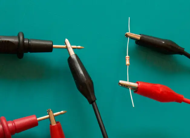
If yous do not take croc-clip wires but apply fingers and thumbs to pinch a probe to each stop of the resistor wires. If you are measuring a resistor already in a circuit y'all must turn the power off before measuring.
Checking Continuity
Turn off and disconnect circuit before checking
This is related to resistance. Expert continuity has very depression to zero resistance – the electric current flows without resistance. If you plow the selector to the resistance position (4 clicks from off) the display should show 0.L M Ω (Overload), indicating massive resistance or no connection.
If you then touch the ends of the probes together the display will change to null or 0.1 Ohm indicating no resistance or very adept continuity – a good connexion. To save you having to keep looking at the screen every bit you probe a circuit board, checking if sure pins are properly connected, you can get the meter to beep if in that location is good continuity. Select resistance with the rotary switch and press the select button until the continuity symbol appears on the screen and the meter beeps.
Check by touching the ends of the probes together to get a beep. Hold the probes against the reverse ends of a doubtable length of wire. If you go a beep, continuity is skilful. If the meter remains silent the cable is broken at some betoken. (This meter will beep if the resistance is less than about 30 Ohms. If you lot desire a really good indication, read the resistance rather than listen for a beep. I accept another meter which has a beep threshold of 120 Ohms. Check your manual to find the threshold value for your instrument.)
This facility is very useful if y'all have but had to solder a set of pins onto a new microcontroller board such as an ESP 32 or a modest Arduino board. You need to check that in that location is no continuity betwixt adjacent pins because too much solder has flowed and you accept bridged them. Here you set up the meter for continuity and press the probes on the pinnacle of each pair of adjacent pins in turn. If you take washed a skilful job y'all should not get a beep.
In a similar way you can check for a required proficient connection between a pin on your microcontroller and the leg of a component on a circuit lath. (There may be a dry joint or a wrongly positioned cut of a copper track on your board upsetting the connection.)
Adjacent copper strips on stripboard circuits should not normally exist continued. You can use continuity to bank check for solder blobs bridging adjacent strips or poorly fabricated breaks in strips, allowing current to menses in the incorrect place.
Reading Current
To read a current your meter must exist inserted into the circuit in series rather than in parallel. Your meter becomes office of the circuit, replacing a connection wire. On a breadboard circuit, this is quite easy to accomplish past replacing a single jumper wire with two and inserting the meter in the join. On a stripboard or printed circuit board, you have to cut a track and insert test bespeak pins for the meter, which can later be joined with a jumper connectedness once the meter has been removed.
When connecting the meter, you lot should consider the direction of the current catamenia. The RED probe would normally be connected to the higher potential. For example, to read the total electric current flowing through a circuit, break the GND return wire, and connect the BLACK probe nearer to the GND pivot on the Arduino and the RED probe towards the circuit board. If you get the polarity wrong yous will go a negative reading.
My meter has three selection positions on the dial for reading current, µA, mA and A. If you look the electric current to be greater than 200 mA the Ruby-red probe has to be moved from the normal INPUT socket to the A socket, which has a higher rated fuse, and use the A choice on the dial. We will be expecting less than 200 mA, so we can leave information technology in the INPUT socket and select mA. Check that it defaults to DC.
A Applied Example Projection
I'm going to build a simple circuit and read the resistance, and then current and voltage modify while it is running. This is a very unproblematic build including a button switch, an LED and two resistors, 10K and 560 Ohm.
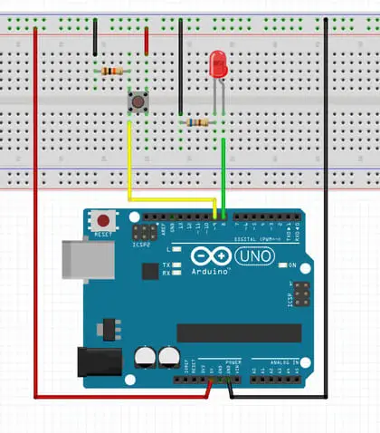
This circuit shows a 680 Ohm where I used a 560 Ohm resistor, on the correct, between the LED and GND. (Fitzing did non have a 560 Ohm resistor bachelor in the bin.)
I had previously congenital it on a stripboard.
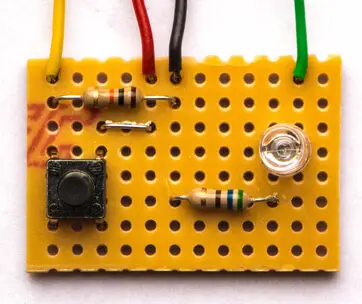
With the excursion not continued to the Arduino, I measured the resistance of the resistors and got 9.89K Ohms for the 10K and 554 Ohms for the 560 Ohm resistor. (Recollect that resistors accept a tolerance of five% or ten%. These were both within tolerance) The probes were pressed to the wires at either end of the components.
I connected the circuit to the Arduino and ran the post-obit simple script which switches on the LED when the switch is closed. A pull-down 10 Thou ohm resistor was used and then that the switch value was TRUE (1) when pressed. The LED, light-green wire, was continued to pin 9 and the switch, xanthous wire, was connected to pivot 8 of the Arduino UNO.
// Multimeter Excursion Testing Project // Tony Goodhew - 12 Aug 2020 // Tutorial45.com // LED with 560 Ohm resistor on pin ix // Button switch with 10K Ohm pull-downwardly resistor on Pin 8 int LED = 9; // Dark-green wire int push = eight; // Yellowish wire void setup() { pinMode(LED, OUTPUT); pinMode(push button, INPUT); } void loop() { int button_Value = digitalRead(button); // Read push digitalWrite(LED, button_Value); // Adjust LED delay(50); } Resulting Measurements
- The voltage betwixt the 5V and GND pins was 4.99V without the board continued and this dropped to 4.98 V when the board was continued and the switch open or closed.
- The voltage dropped across the 10K Ohm pull-downwards resistor was 4.98 V as the switch was closed.
- With the script running the voltage drop across the 560 Ohm LED resistor was ii.264 Five when the LED was ON.
- To mensurate the current flowing through the LED and the 560 Ohm resistor I put the meter between pin 9 (Cerise probe) and the dark-green wire (BLACK probe) and found that the electric current was iv.09 milliamps.
- To measure the electric current of the whole lath I put the meter between the black wire (RED probe) and the Arduino GND pin (BLACK probe) and got 4.59 milliamps.
- An LED is a diode and then with the circuit unpowered and disconnected from the Arduino I put the Cherry-red probe on the end of the green wire, LED anode, and the Black probe on the cathode of the LED, and so selected the diode option with the pick switch and button. The reading was two.299 V – judge forward voltage of the LED.
Conclusions
I take always found access to a multimeter very useful. How exercise I really utilize it?
- Checking the country of batteries – OK, recharge, or supplant?
- Checking the value of resistors earlier I solder them in identify.
- Continuity checking after soldering or fault-finding. Is in that location a expert connection between these two points?
- Eliminating unwanted connections because of an excess of solder or poor copper strip cutting when making, or forgetting to make, an essential break in a runway.
- I hardly ever measure a electric current.
Final Thoughts
- The instruction manual which comes with your meter is a vital source of information and yous should read information technology advisedly in example your meter differs slightly in its means of working from mine. (Why is the impress always so small? This is much easier to read: https://static.astroai.com/transmission/Astroai-Digital-Multimeter,-Trms-4000-Counts-User-Manual.pdf then download a pdf version of your manual, if bachelor.)
- Exist very conscientious when working with 120 or 240V Ac. It can KILL!
Source: https://tutorial45.com/how-to-use-a-multimeter-using/
0 Response to "How to Read Mv on a Multimeter"
Post a Comment